Orthopedic implants can transform mobility, yet their MRI behavior requires careful, device-specific evaluation. The question “What factors affect the compatibility of orthopedic implants with MRI machines” has no single answer. Material composition matters, but it is only one part of the assessment. Implant shape, size, location, fixation method, and surrounding tissue can also influence safety.
At 1.5-tesla or 3-tesla, MRI creates strong static magnetic fields, rapidly changing gradients, and radiofrequency energy. These forces may produce movement, electrical currents, or localized heating in certain implants. Metallic components can also create image distortion near the knee, hip, spine, or shoulder. Dr. Frank G. Shellock, a leading MRI safety researcher, has emphasized: “MRI safety depends on the specific device, the specific scanner, and the specific conditions of use.” That principle remains practical at the scanning console.
This guide examines ten factors affecting orthopedic implant MRI compatibility. It considers implant materials, geometry, labeling, magnetic attraction, torque, heating, electrical conduction, artifact production, scanner strength, and clinical positioning. The patient’s surgical history also deserves attention. A healed implant may behave differently from a recently placed device. Small details matter.
No checklist is perfect. Manufacturer information can be incomplete, outdated, or difficult to locate. Some implants have mixed components from different suppliers. That uncertainty should never be ignored. Radiologists, MRI technologists, surgeons, and patients must verify the exact implant model before scanning. Safe decisions depend on documented evidence, controlled settings, and careful professional judgment—not assumptions based only on the word “titanium.”
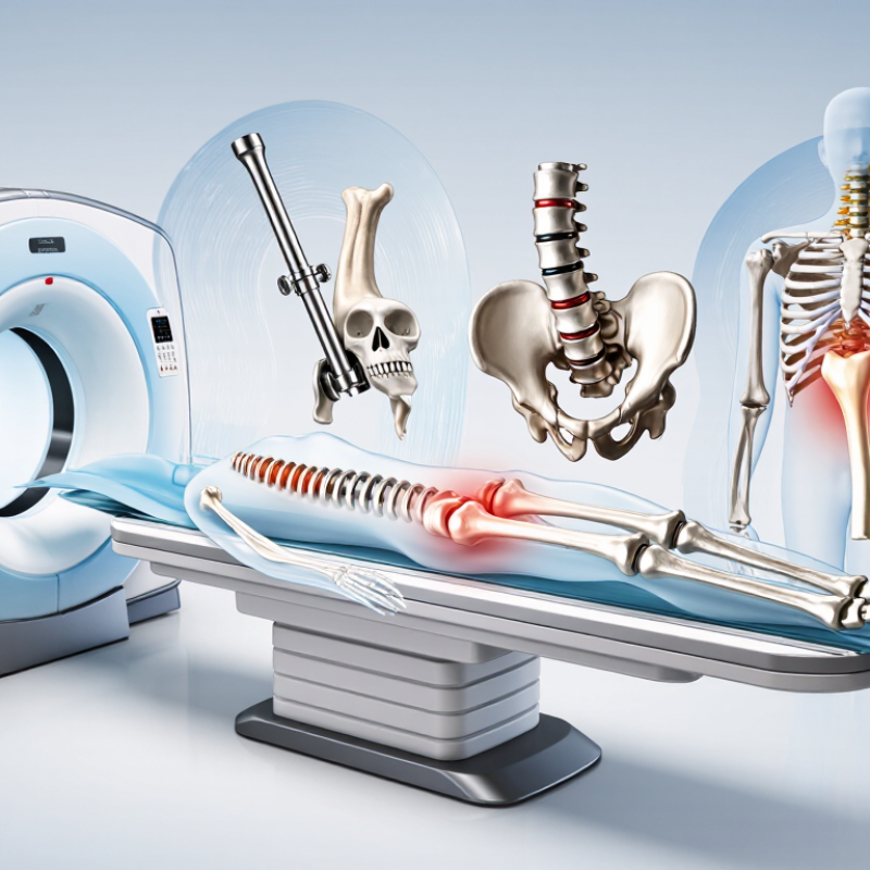
Orthopedic implant MRI compatibility means the implant can enter an MRI environment under defined conditions without creating unacceptable risks.
These risks include movement, heating, vibration, malfunction, or image distortion. The definition is conditional, not absolute. An implant may be safe at 1.5 tesla but require different limits at 3 tesla.
ASTM F2503 classifies devices as MR Safe, MR Conditional, or MR Unsafe. MR Conditional means safety depends on specific conditions, such as magnetic field strength, spatial gradient, scan duration, and radiofrequency exposure. The American College of Radiology Manual on MR Safety recommends verifying the implant model, materials, and tested conditions before scanning. A patient’s operative record matters more than memory.
FDA MRI safety guidance identifies static fields, gradient fields, and RF energy as major exposure factors. These fields can heat metallic components or produce uncomfortable sensations. Titanium often reduces magnetic attraction, but it does not eliminate heating or artifact risks.
The implant’s shape, fixation method, and surrounding tissue also matter. ASTM testing does not perfectly reproduce every clinical situation. That limitation deserves attention.
A 2024 ACR safety report stresses documented screening and trained supervision, especially when implant information is incomplete. In practice, compatibility should be treated as a verified operating condition, not a permanent label.
Implant materials strongly influence MRI safety, but material alone never tells the whole story. Titanium and many titanium alloys have low magnetic susceptibility, so they usually create limited attraction and smaller image artifacts. Cobalt-chromium alloys are also commonly considered weakly magnetic, although their composition and manufacturing history matter. Stainless steel requires closer review. Some grades become more magnetic after cold working or machining.
Nonmetallic materials, such as ceramic and PEEK, usually produce minimal magnetic interaction. However, an implant may include metal screws, markers, wires, or coatings. Those small parts can affect heating, movement, and image quality. A titanium implant is not automatically artifact-free. Its shape, size, and position can still obscure nearby anatomy. This is where assumptions become risky.
Tips: Confirm the exact implant model, material, and MRI conditions before scanning. Check the official device documentation and the facility’s current safety protocol. Look for labeling such as MR Safe or MR Conditional, rather than relying on a general material name. Remember that “MR Conditional” includes limits for field strength, specific absorption rate, and scan duration. Documentation may be incomplete after older surgery, which is an uncomfortable but important problem. When details remain uncertain, involve a radiologist, MRI safety specialist, and the orthopedic team. Clear records are often more valuable than confident guesses.
An implant is not simply “metal in a scanner.” Its design controls heating, torque, and image distortion. Shape matters. Long conductive paths can support stronger induced currents. Porous structures may reduce weight, yet their geometry can complicate safety testing. Materials, coatings, connectors, and fixation screws also influence performance.
Size changes the exposed surface and artifact pattern. Larger implants may create wider signal voids, especially near the joint or spine. However, size alone does not determine risk. FDA MRI safety guidance identifies heating, force, torque, malfunction, and artifacts as key hazards. ASTM F2182-19a uses a 15-minute radiofrequency exposure framework for measuring heating near passive implants. That is a test condition, not a guarantee.
Location adds another layer. A hip implant may obscure the pelvis, while spinal hardware can hide the operative level. A smaller implant near the imaging field may matter more than a larger implant farther away. Field strength and scan sequence can change the result. The ACR Manual on MR Safety recommends verifying implant identity, location, and exact MR conditions before scanning. In practice, incomplete surgical records remain a weak point. I have seen “titanium” treated as sufficient information, although it says nothing about geometry, fixation, or labeling. A careful review should compare the implant’s documented conditions with the planned scanner, body region, and sequence.
Top 10 Factors Affecting Orthopedic Implant MRI Compatibility
MRI compatibility is not a simple yes-or-no label. Implant material, shape, fixation, location, and scan conditions all influence safety. Most passive orthopedic implants remain stable, but uncertainty can appear with complex components, loose fragments, or unknown surgical history. Never rely on memory. Confirm the implant model, implantation date, field strength, and approved scanning conditions before imaging.
Heating is a key concern. Radiofrequency energy may warm conductive parts, especially near edges, joints, or extended components. Higher specific absorption rates, longer sequences, and poor patient positioning can increase this effect. Displacement and torque are less common with firmly fixed implants, yet they deserve attention when fixation is weak or the implant is recently placed. Patients should report warmth, pulling, vibration, or pain immediately. Small details matter.
Artifacts can obscure bone, soft tissue, or the implant interface. Metal may create signal voids, distortion, and bright areas that resemble pathology. The affected region depends on implant composition, geometry, orientation, and MRI sequence. Radiologists may adjust bandwidth, slice direction, or sequence selection, but image quality can still be limited. A missing operative record complicates decisions. Care teams should document symptoms, verify technical conditions, and reassess uncertain cases rather than assuming every orthopedic implant behaves alike.
The chart ranks the relative priority of key MRI-safety factors on a 0–10 screening scale. The ranking reflects established MRI safety principles involving radiofrequency heating, magnetic-force displacement, torque, image artifacts, implant geometry, fixation, scan conditions, and patient-specific circumstances. Scores are not measured probabilities and must not replace the implant’s labeling, manufacturer instructions, or site-specific MRI safety assessment.
MRI risks can vary with field strength, spatial-gradient field, SAR, pulse sequence, scan duration, implant configuration, and the time since implantation. “MR Conditional” status applies only under the conditions specified for the particular implant.
Top 10 Factors Affecting Orthopedic Implant MRI Compatibility
Evaluating an orthopedic implant begins with verified device records, not assumptions. The radiology team should confirm the implant’s exact model, material, location, and implantation date. MRI safety labeling may specify field strength, scan limits, positioning, or special operating conditions. A titanium component can behave differently from a mixed-metal assembly. Small details matter.
Patient-specific risks also require careful review. Previous surgeries may have left wires, fragments, or temporary components that are missing from the patient’s memory. Pain, swelling, unstable fixation, infection, and poor bone healing can change the risk assessment. The team should compare imaging history with surgical notes and examine the planned body region. Artifact may reduce diagnostic quality, especially near the implant. Heating and movement risks are uncommon, but they must not be dismissed. I have seen incomplete records create unnecessary uncertainty.
Tips: Ask for the implant card or operative report before scheduling. Confirm the scanner’s field strength and operating limits. Remove external metal items. Explain expected sensations clearly. During scanning, report unusual heat, pulling, or increasing pain immediately. A pause is safer than silent discomfort. Staff should monitor high-risk patients closely and document every decision. When records conflict, a qualified radiologist, MRI safety specialist, and orthopedic clinician should review the case together. Erotiske? No. Never rely on a generic “metal is safe” statement.
| No. | Compatibility Factor | Why It Matters | Evaluation Procedure | Patient-Specific Safety Considerations | Typical Control Measures |
|---|---|---|---|---|---|
| 1 | Implant labeling and MR status | An orthopedic implant may be MR Safe, MR Conditional, or of unknown status. MR Conditional devices are safe only under specified conditions. | Review the implant card, operative report, medical records, and current manufacturer labeling. Confirm the exact model, component, configuration, and applicable field-strength conditions. | Do not assume that all implants in the same anatomical region have identical MRI conditions. If the device cannot be identified or its conditions cannot be verified, treat it as an unknown implant and obtain specialist review. | Use only the documented conditions; defer or modify the examination when required information is unavailable. |
| 2 | Magnetic susceptibility and magnetic force | Ferromagnetic materials can experience translational force or torque in the static magnetic field, creating a risk of movement, displacement, or discomfort. | Assess material composition and conduct standardized testing for displacement force and torque when required by the device evaluation protocol, commonly using methods aligned with ASTM F2052 and ASTM F2213. | Risk may be more significant soon after implantation, before adequate bone ingrowth or soft-tissue stabilization. Consider fixation quality, implant location, and recent revision surgery. | Confirm acceptable force and torque results and observe the patient for pain or unusual sensations during scanning. |
| 3 | Radiofrequency-induced heating | MRI radiofrequency energy can heat conductive implants and adjacent tissue. Heating depends on implant geometry, orientation, material, sequence, and scanner conditions. | Use validated phantom testing under worst-case conditions, including relevant transmit-coil configuration, field strength, landmark position, sequence type, and whole-body or local SAR limits. Methods may be based on ASTM F2182. | Patients with reduced sensation, neuropathy, sedation, impaired communication, or compromised skin integrity may not reliably report heating or pain. | Apply the specified SAR or B1+rms limits, use normal operating mode when required, and stop the scan if the patient reports warmth or discomfort. |
| 4 | Implant geometry, length, and conductive loops | Long conductive components, cables, wires, rods, and loop-shaped structures can increase local RF coupling and heating. | Document the complete construct, including rods, screws, plates, cables, connectors, and accessory components. Evaluate the full assembly rather than isolated parts when the implant is used as a system. | A mixed or revised construct may have different MRI behavior from the original implant. Positioning and the distance between the implant and the transmit coil may also affect risk. | Verify the complete configuration and follow the most restrictive condition applicable to any component. |
| 5 | Gradient-induced stimulation and vibration | Time-varying gradient fields can induce electrical currents in conductive structures and may produce vibration, peripheral nerve stimulation, or discomfort. | Review device-specific gradient limits and assess induced voltage or related behavior using appropriate laboratory methods. Confirm compliance with the scanner's dB/dt and operating-mode limits. | Patients with pain, neurological disease, muscle spasticity, or limited communication may require closer observation and a lower threshold for stopping the scan. | Use approved gradient conditions, provide communication and emergency call access, and monitor for twitching, tingling, or unexpected vibration. |
| 6 | Image artifact and diagnostic field of view | Metal-related susceptibility artifacts can obscure anatomy, reduce diagnostic quality, and conceal pathology near the implant. | Estimate artifact size and image-quality impact using representative sequences, implant orientation, receiver coil, field strength, and anatomical region. Compare metal-artifact-reduction techniques where available. | Determine whether MRI is clinically necessary and whether another modality may better answer the clinical question, particularly when the target anatomy is adjacent to metal. | Optimize bandwidth, view-angle, voxel size, echo timing, and metal-artifact-reduction techniques without exceeding implant limits. |
| 7 | Field strength and scanner configuration | An implant's conditions may differ between 1.5 T and 3 T systems, and may depend on scanner type, transmit coil, spatial gradient, and operating mode. | Match the intended examination to the exact scanner parameters. Record static field strength, maximum spatial gradient, RF transmit configuration, SAR or B1+rms, and gradient limits. | A scan that is acceptable at one field strength or on one scanner may not be acceptable under different conditions. Transfers between facilities require a new verification of scanner compatibility. | Use a documented scanner-specific checklist before positioning the patient in the magnet room. |
| 8 | Implant fixation, healing stage, and mechanical stability | MRI does not normally cause orthopedic implants to fail mechanically, but pain, loosening, fracture, infection, or incomplete healing can change the clinical risk assessment. | Review surgical date, implant location, postoperative imaging, fixation method, revision history, and current symptoms. Obtain orthopedic input when stability is uncertain. | Recent surgery, suspected loosening, nonunion, unstable fracture, infection, or severe postoperative pain may warrant additional clinical evaluation before MRI. | Confirm clinical stability and use the shortest appropriate protocol; do not use MRI compatibility as a substitute for surgical assessment. |
| 9 | Additional implants, retained fragments, and external equipment | The overall MRI risk is determined by every relevant implant, retained fragment, accessory device, and monitoring component, not only the primary orthopedic implant. | Perform a complete implant and foreign-body screening interview, review prior imaging, and assess retained wires, bullet fragments, fixation hardware, medication devices, and monitoring equipment. | Unknown metallic fragments, electrically active devices, abandoned leads, or components near critical anatomy may introduce risks that override the orthopedic implant assessment. | Identify and clear every item before scanning; use only accessories labeled for the planned MRI environment. |
| 10 | Patient condition, positioning, and monitoring capability | Patient-specific factors can affect the ability to detect heating, pain, pressure, movement, or other adverse sensations during the examination. | Assess sensation, cognition, communication, mobility, skin condition, body habitus, pain level, anxiety, sedation status, and ability to use the alarm system. Plan padding and positioning to avoid skin-to-skin loops and pressure points. | Extra precautions may be needed for children, sedated patients, patients with neuropathy or reduced sensation, and those unable to communicate reliably. Prevent contact with the bore and avoid conductive loops. | Provide two-way communication, appropriate padding, visual or physiologic monitoring when indicated, and continuous observation according to institutional policy. |
It means the implant can enter an MRI scanner under verified conditions. Safety is conditional, not permanent. Field strength, scan duration, and radiofrequency exposure matter.
No. Many fixed implants remain stable, but each model needs verification. Mixed metals, loose fragments, or unknown surgical history can change the decision.
Bring the implant card, operative report, or surgical records. Include the implant model, material, location, and implantation date. Memory is unreliable.
Yes. Radiofrequency energy may warm conductive parts. Risk can increase with longer sequences, higher exposure settings, or poor positioning. Report warmth immediately.
Report unusual heat, pulling, vibration, pain, or swelling. Do not stay silent. A pause is safer than tolerated discomfort.
Movement and twisting are uncommon when fixation is firm. Risk may increase with loose fixation, recent surgery, fragments, or poor bone healing. The team must assess these details.
Metal may create dark gaps, distortion, or bright areas. These effects can hide bone, soft tissue, or the implant boundary. Sequence adjustments may help, but not always.
The MRI team should not guess. They may compare surgical notes, earlier images, and clinical findings. A radiologist and orthopedic specialist may need to review the case.
No. Titanium often reduces magnetic attraction, but heating and image artifacts remain possible. Shape, fixation, nearby tissue, and scanner settings still matter.
Confirm the scanner’s field strength and implant conditions. Remove external metal items. Explain previous surgeries honestly. Some records will be incomplete. That is frustrating, but review is necessary.
Orthopedic implant MRI compatibility refers to whether an implant can safely remain in the body during magnetic resonance imaging without causing harmful movement, excessive heating, or severe image distortion. What factors affect the compatibility of orthopedic implants with MRI machines? Key considerations include the implant’s material and magnetic properties, such as whether it is strongly attracted to magnetic fields or conducts energy that may generate heat. The implant’s design, size, shape, and anatomical location also influence safety and image quality, particularly when it is close to the area being examined.
MRI-related risks may include magnetic displacement, radiofrequency heating, vibration, and artifacts that obscure diagnostic information. Compatibility should therefore be evaluated through standardized testing, technical documentation, and appropriate scanning conditions. Patient-specific factors, including implant age, fixation, surrounding tissue, and the presence of additional medical devices, must also be reviewed. A careful assessment by qualified healthcare professionals helps determine whether MRI is appropriate and which precautions are necessary.

Axton Orthopedic Implants